
Shot Blasting Rubber Track Cleat Spacing: Turning a Custom Drawing Conflict into Customer Trust
A South Korean shot blasting equipment manufacturer requested a customized rubber track. After technical review, our team revised the cleat spacing to approximately 800 mm to better suit the equipment’s tumbling mechanism, wear conditions, and production requirements.
To protect confidentiality, this case study omits the customer’s company name, contact details, order value, machine serial number, and identifiable drawing information.
The starting point: a custom shot blasting track drawing
The customer supplied an engineering drawing for a rubber track used in a tumble shot blasting machine. The drawing included the track dimensions, cleat geometry, hole layout, and the customer’s preferred cleat arrangement.
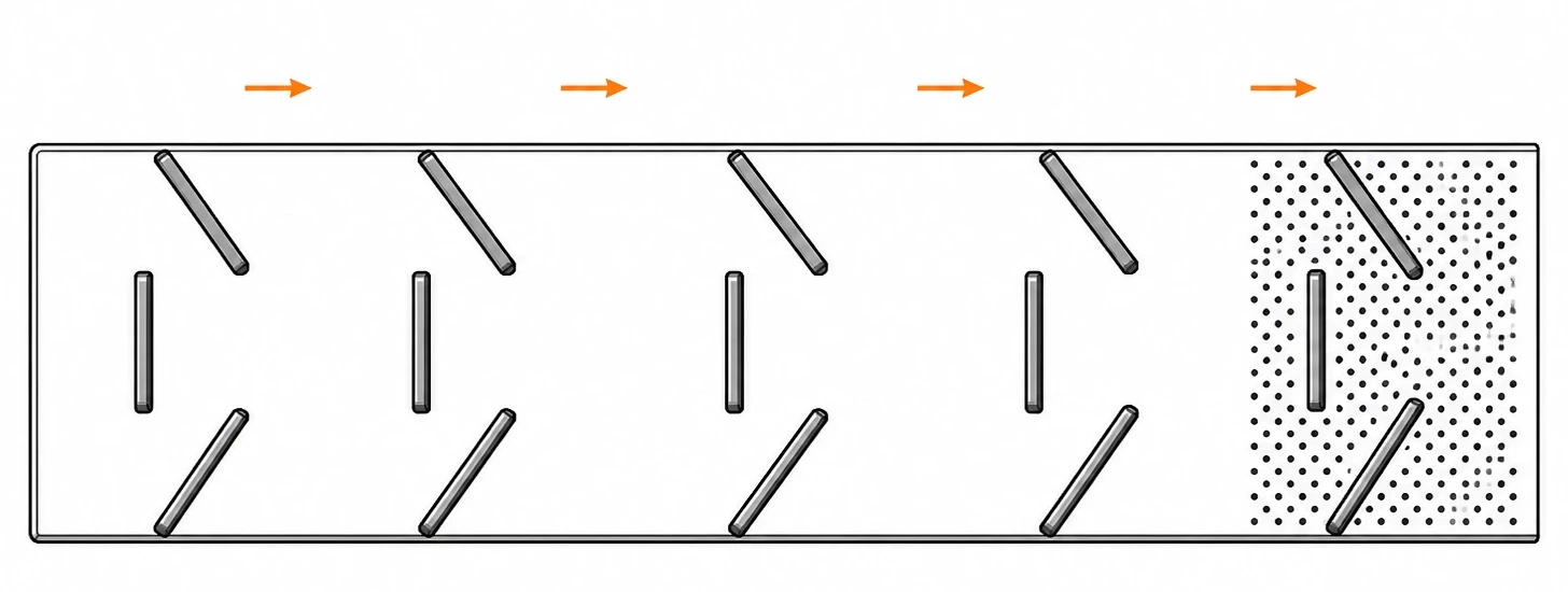
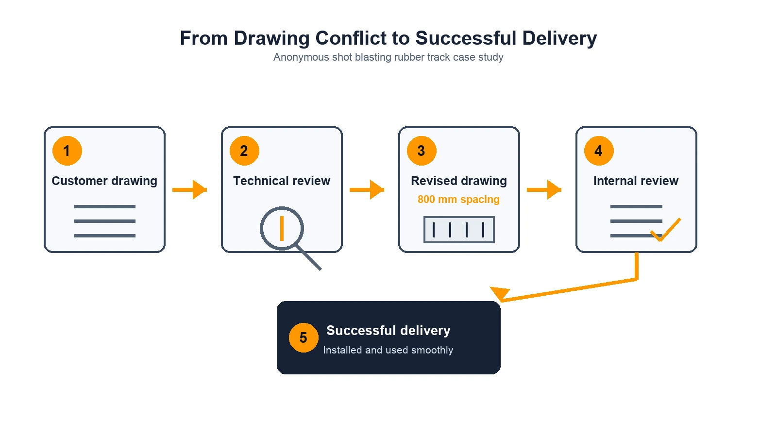
After reviewing the drawing against the available tooling, the machine’s rotation direction, the workpiece loading pattern, and the expected shot-blast conditions, our technical team concluded that the production drawing needed an adjustment before manufacturing.
The technical recommendation: revise the cleat spacing to approximately 800 mm
The requested cleat arrangement could not be reproduced exactly within the available tooling and production conditions. Rather than treating this as a simple “cannot make” response, our technical team reviewed the customer’s actual equipment and proposed a revised spacing of approximately 800 mm.
The customer was understandably cautious because the original drawing and the revised production recommendation were not identical. The key question was whether the revised spacing would affect workpiece tumbling, equipment operation, or track durability.
Why the 800 mm spacing can suit tumble blasting
Workpieces tumble as a batch, not as individual items
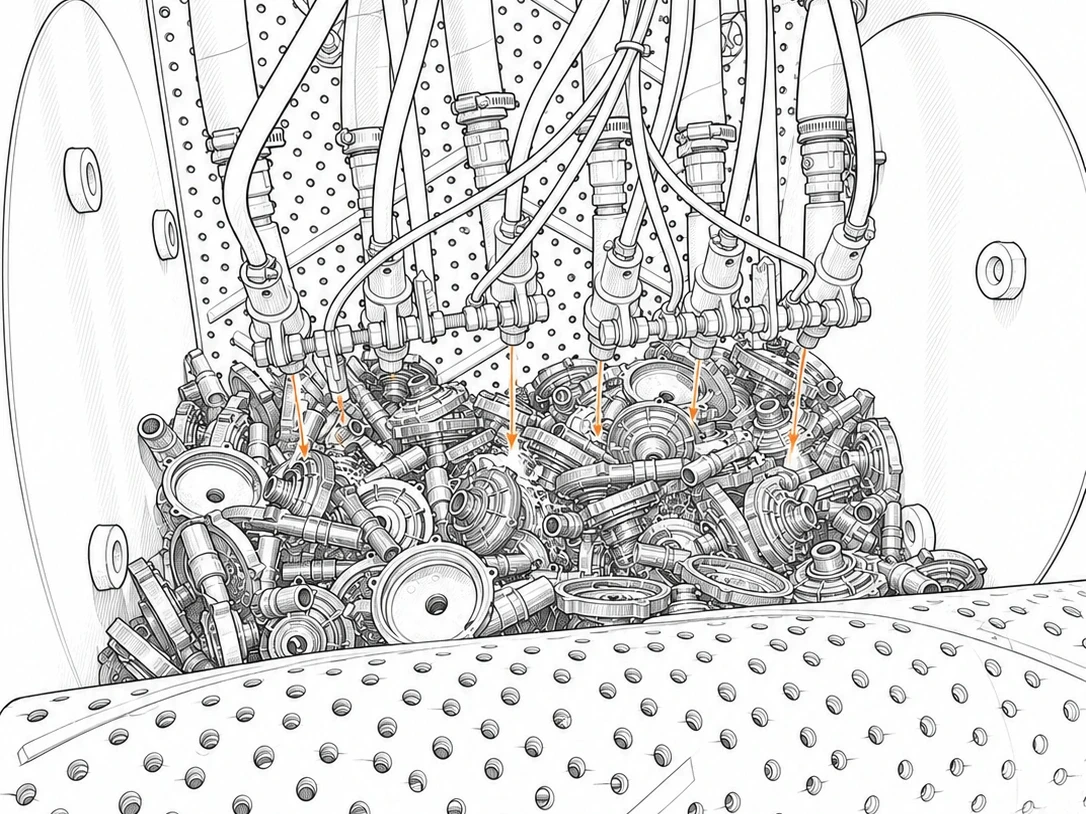
Inside a tumble blast machine, the track carries many workpieces at the same time. The parts roll and rotate through their combined weight, gravity, collision, and friction with one another.
The surface cleats mainly help initiate upward movement and prevent the load from slipping backward at the bottom of the track. They are not intended to form a separate pocket around every individual workpiece.
Wider spacing can reduce unnecessary shot impact
If raised cleats are placed too densely, more rubber projection area is exposed to direct steel-shot impact. That can accelerate wear at the cleat faces and roots, especially with heavy or sharp workpieces.
The approximately 800 mm spacing was selected to preserve anti-slip guidance while allowing a more open tumbling path and reducing unnecessary direct impact. The exact suitability still depends on cleat geometry, workpiece size, batch weight, speed, shot conditions, and the complete machine design.
Helping the customer communicate the decision internally
To support the customer’s internal communication and review—including reporting to the relevant engineering department and management—we shared the technical reasons behind the drawing spacing and why it was more suitable for field operation and durability.
Technical advantages and application basis of the spacing shown on our drawing
Optimized batch-tumbling mechanism: the machine processes many workpieces as a batch. The parts roll through their combined contact and collision, while the raised profiles guide the load and help prevent slipping when tumbling begins. If the spacing is unnecessarily narrow, workpieces may become trapped between the profiles and the tumbling movement may be restricted.
High quality and longer service life: when raised profiles are too close together, steel shot can repeatedly strike the rubber projections and accelerate wear. The spacing shown on our drawing reduces unnecessary direct impact and is intended to extend overall track life.
Application experience: the proposed configuration reflects a mature specification used in OEM and export supply for established surface-treatment customers in Japan and South Korea, as well as Southeast Asian applications. We hope this information supports your internal communication and review.
Once the drawing is finally confirmed, we will begin careful production immediately and share the production schedule as soon as it is available.
The result: accepted, delivered, and used successfully
After reviewing the explanation, the customer accepted the proposed 800 mm cleat spacing and confirmed that production could proceed according to the revised approval drawing.
We arranged production, controlled the dimensions and finishing quality, and kept the customer informed of the production schedule. The track was completed, delivered, and successfully received by the customer.
The track was then installed and used smoothly. The revised spacing reduced unnecessary cleat exposure to direct steel-shot impact, supporting longer service life under the customer’s operating conditions.
Send the machine details for technical review
Share the machine model, track width and perimeter, thickness, cleat layout, hole pattern, workpiece details, shot media, photos, drawings, or an existing sample.
